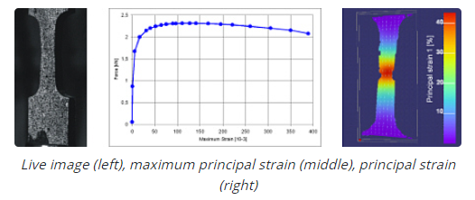
DIC offers characterization of material parameters far into the range of plastic deformation. Its powerful data analysis tools allow the determination of the location and amplitude of maximum strain, which are important functions in material testing.
")
Digital 3D Image Correlation System (DIC)
Headspace Analyser
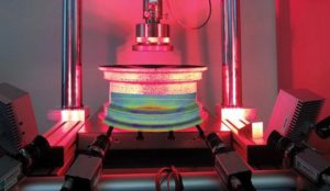
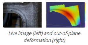
DIC is ideal for fracture mechanics investigation. The full-field measurement delivers exact information about local and global strain distribution and crack growth, and can be used for the determination of important fracture mechanics parameters.
Full-field, non-contact, three-dimensional image analysis

Fracture Mechanics Investigation
Image Correlation techniques have proven to be a flexible and useful tool for deformation analysis. With the use of two cameras, even three-dimensional studies can be carried out. The principle of this technique is quite easy to understand and opens a nearly unlimited range of applications.
In classical image correlation, the deformation of an object is determined by observation with a CCD camera. Then, a digital image correlation process determines the shift and/or rotation and distortion of small facet elements determined in the reference image. Such correlation algorithms can determine the maximum of the displacement with an accuracy of up to 1/100 pixel. This procedure allows the determination of the object deformation in a plane parallel to the image plane of the camera.
Reflow solder machines are used in applications where production line flow solder machines require a controlled atmosphere within the pre-heat tunnel, to achieve optimum solder connections for highly reliable printed circuit boards used in the electronics industry.
Components are soldered onto printed circuit boards at a high speed for use in computers, mobile phones, PDA devices and general electronic circuit cards. To facilitate an ideal solder connection, whilst minimizing oxidization, the process requires gas flushing, usually with nitrogen, to achieve a low level of oxygen.
Our oxygen sensor and nitrogen control system can accurately measure the oxygen levels and ensure real-time control of the exact amount of nitrogen flushed through the solder machine. This is a critical part of the process as, in addition to requiring the optimum soldering environment, nitrogen wastage is expensive.

Oxygen Sensor and Nitrogen Control System

Nitrogen Saving Reflow Soldering System
Reflow Soldering for PCB Assembly

Reflow Soldering for PCB Assembly
Volt endurance testing is used for evaluating the dielectric strength (volt endurance/ volt destruction) of solid electric insulating material. By exchanging the electrodes, the tester can also be used for board, sheet, textile, film, tape, tube, varnish, and paint. Recent applications also include insulating film in lithium-ion batteries. After setting the specimen between the two electrodes, voltage is applied mid-air or in-bath until the specimen insulation destructs. The results are evaluated either by the insulation strength or destruction voltage level. The tester is capable of both the short-time test and step-by-step test. The tester can also be used for enamel coatings using the twist pair method by exchanging the electrodes.
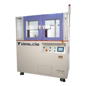
Volt-Endurance and Destruction Tester

Endurance Test
Endurance Test
Apply and increase voltage at a constant rate to a certain point and maintain the voltage. It simulates the actual usage of the specimen. However, higher voltage can be applied to test for its maximum endurance.


Destruction Test
Destruction Test
Apply and increase voltage at rate to the specimen’s destruction point. Then, measure the maximum voltage.

Destruction Test (Step by Step)
Destruction Test (Step by Step)
Step by step method is conducted as normal destruction test. It increases voltage to 40% of the specimen destruction point and maintains for 20 seconds, then steps up to the destruction point. It is closer to simulate for the actual condition not only to the destruction voltage but also for short-time endurance at the same time.
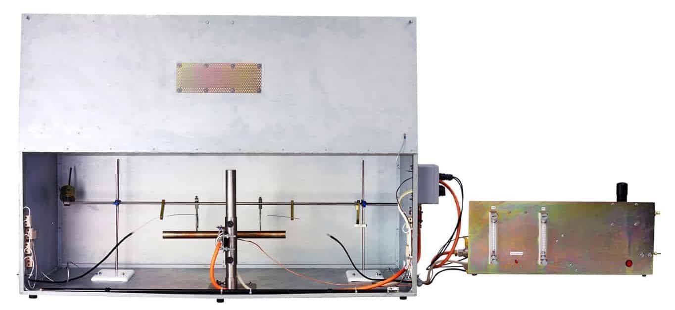
This is a test for the vertical flame propagation of a single insulated wire or cable which is a bench scale test to determine the resistance of a single cable to a 1kW flame application. The apparatus is supplied as a complete system incorporating all the features necessary for ease of use and safety. It conforms to IEC/ EN 60332-1-2 (flame propagation) and IEC/ EN 60332-1-3 (test for flaming droplets).

Flame Propagation Test for a Single Insulated Cable
The European Commission and The European Cable Industry (EUROPACABLE) are finalizing Classification criteria for evaluating electric cables throughout Europe under the Construction Products Directive (CPD). The Classification utilizes the results obtained from traditional IEC 60332-3 test equipment fitted with heat and smoke release measurement instrumentation. The former is calculated by continuous measurement of the oxygen consumed and carbon dioxide generated in the combustion process.
Modifying Existing IEC 60332-3 Apparatus To Measure Heat Release
Conversion of existing IEC 60332-3 apparatus to measure heat release is accomplished by fitting a small instrumented section of ducting into the exhaust system of the rig and using this with associated gas analysis instrumentation and software and a modified test protocol. The duct section houses all gas sampling probes, temperature and mass flow probes needed, and the smoke measuring system.

Burning Behavior of Bunched Cables
These are the BS 6387 test apparatus required for testing cable circuit integrity under fire conditions. The apparatus is supplied with ability to assess:
Resistance to Fire Alone (IEC 60331-11 / BS 6387 Protocol C)
Resistance to Fire with Water (BS 6387 Protocol W)
Resistance to Fire with Mechanical Shock (BS 6387 Protocol Z)

Circuit Integrity Under Fire Conditions Apparatus
Circuit Integrity Under Fire Conditions Apparatus
Circuit breakers are ubiquitous wherever there are electrical circuits that need protection against
excess current caused by an overload or short circuit. They range in size and capacity from devices the size of a fingernail used for semiconductor protection to devices as large as a truck designed to protect the high voltage circuits that supply power to cities.
Given the high voltages and currents associated with high power circuit breakers, research and development activities for these devices have the potential to be extremely hazardous; because they haven’t yet been thoroughly characterized at this stage, circuit breakers that are overstressed can explode and or burn.
Our data acquisition solution offers equipment and software optimized for such high power testing applications which is made up of three main components: high-speed transient recorder & data acquisition system, high-voltage / high-power isolated digitizer and high-speed data acquisition software.

High Speed Transient Recorder & Data Acquisition System

Testing High Power Circuit Breakers Safely
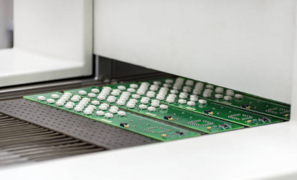
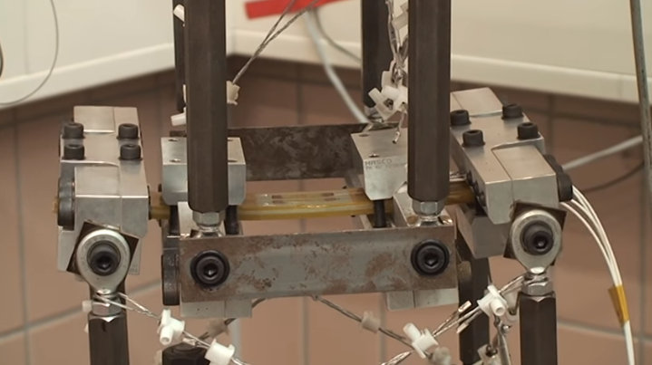
Printed circuit boards of electronic components in automobiles, commercial vehicles, or smart phones must withstand harsh conditions in mobile use. Even slight cracks can cause the entire electronics system to fail. To prevent this, manufacturers test the mechanical stability of printed circuit boards.
Printed Circuit Boards (PCBs) are exposed to high mechanical load during the production and mounting process. These single events can pre-damage the board or the components mounted on the board and lead to a failure in the field. By measuring the stress in these processes, you can uncover potential weak points, improve the process and thus help improve the product quality.

Strain Measurement on PCB

PCB Testing with Strain Gauge
- Semiconductor research
- Printed circuit board
- Flex circuiting
- Switches / Buttons
- Tactile feel
- Fine wires and connectors
- Solder fatigue testing

Material and Component Testing / Fatigue Test
Material and Component Testing / Fatigue Test

Material and Component Testing / Fatigue Test
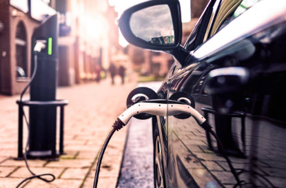
The Isothermal Air Calorimeter utilizes power compensation for measurement of heat flux from electronic devices, lithium ion cells and modules. Its large chamber measures 450 x 400 x 300mm is suitable for a wide variety of electronic components and devices.
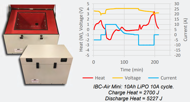
Cycling, Usage and Isothermal Tests for Electronics Components and Devices